Rotary Positioning and Machining
With Advanced Milling and Free Form Machining, you can generate code for the following rotary table configurations:
- 4th-axis positioning for a table whose axis is centered on the X or Y axis of the machine. The center of the primary table's face typically matches the origin of SmartCAM's world coordinate system.
- Rotary contour machining where the rotary axis is centered on the X axis (A rotary axis) or Y axis (B rotary axis). The right-hand rule determines positive rotation, with SmartCAM's world coordinate system being the origin of the rotational axis.
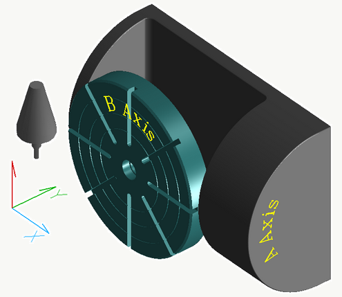
- 5th-axis dual rotary positioning where the table pivots for the 5th-dimensional move. SmartCAM's world coordinate system is commonly the center of the primary table. The offset distance from the pivot point to the center of the primary axis table is set with SMF questions 296 and 297.
A typical B (primary) and A (secondary) axis configuration

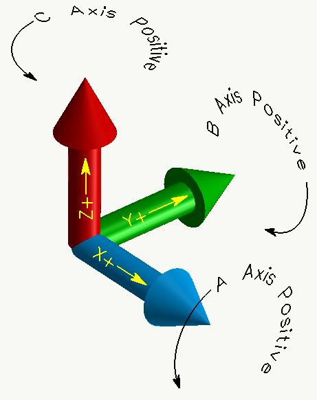
The orientation that Advanced Milling and FreeForm Machining uses for each rotation axis determines the positive rotation angle and related code output. The figure below illustrates the orientations that are used for the A, B, and C axes.
Axis rotation directions

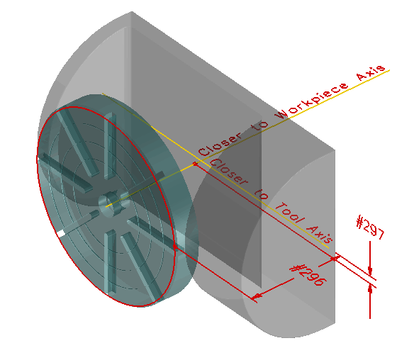
Axis dimensions for dual rotary tables
The distances from the primary coordinate system to the primary axis, and the distance from the primary axis to the secondary axis are determined from questions 296 and 297 of the SMF.

These are the dimensions as measured when the machine is at its home position and the tables at their home, zeroed angles. Question 296 is the dimension from the plane of the primary coordinate system to a parallel plane on the primary axis. Question 297 is the distance of two parallel planes that are perpendicular to the primary coordinate system plane (from question 296), one on the primary axis and the other on the secondary axis.
SMF File Questions for 4th and 5th Axis Positioning
To generate code correctly, you must position the CNC process model so that it aligns with the machine's rotational axes' reference origin. The machine's primary axis centerline and zero position along this centerline (generally the index table's top surface) must correspond to the world coordinate system's origin in the XY plane. The primary axis is usually the axis of a rotary table. For a 5-axis machine, the secondary axis is usually the axis that pivots the rotary table to different orientations about the spindle. The following SMF (Machine Define) questions specify the code format for addressing the primary and secondary axes on the machine:
- 69
- 289-304
- 432-433
- 451-453
Review the various settings and the CGT file reference information to help you understand how to set up a code generator for your machine.
SMF File Questions for Rotary-Axis Machining
The CNC process model for rotary-axis machining should contain wrapped toolpath. The center axis of the tool path must be aligned with the world coordinate system's X or Y axis. Before reviewing the other SMF (Machine Define) questions that relate to rotary-axis machining, check the following questions to make sure you set them properly:
| Question | Recommended Setting |
| 292 | Select either setting 1 (X axis) or setting 2 (Y axis) to identify the primary rotary axis. |
| 303 | Select setting 1 for correct code output. All code values for wrapped toolpath are based on the world coordinate system. |
Other 4th and 5th axis-positioning questions that affect rotary-axis machining include the following:
- 291-292
- 294
- 299-302
- 304
- 432-433
- 451-453
CGT Variables for Multi-axis and Rotary Machining
The following table identifies the CGT variables that affect how SmartCAM generates code for tool and tool plane transitions and rotary-axis machining. Review this list and the table that follows it to get a better understanding of the relationship of each variable to code generation.
| #[XYZ]ST | The retract point in the old tool plane and home position at beginning of program. |
| #[XYZ]PSET | The retract point in the new tool plane. |
| #[XYZ]FO | The tool plane's origin point based on the world coordinate system. |
| #[XYZ]RFO | The tool plane's origin point after any table rotation, based on the world coordinate system. |
| #[IJK]NO | The tool plane's normal (orientation) vector in its original (unrotated) position. |
| #INDX[ABC] | The angles necessary to rotate the tool plane into machining position. |
| #ST[ABC] | The start angle. |
| #[ABC]DIR | The direction of rotation. |
| #WKPLN | The name of the new tool plane. |
| #WKSCHG | A flag indicating a tool change and tool plane change combined.
0=Tool change or tool plane change 1=Tool change and tool plane change This can be used by CGT file logic in the @TOOLCHG or @START section to sense when a tool plane change is combined with a tool change. Typical use is to exit CGT sections early or to call another CGT section. |
| #TINDX | A flag distinguishing tool plane transition types.
0=No tool plane change 1=Transition between parallel tool planes with the same origin 2=Transition between parallel tool planes with different origins (3-D offset) 3=Transition between nonparallel planes with the same origin (index move) 4=Transition between nonparallel tool planes with different origins (index move and 3-D offset) Use this variable with CGT file logic to determine when it is appropriate to exit CGT sections early or to call another CGT section. For example, if you wanted to use the @WKSYS section when a tool plane change took place without an indexing move. |
The following table represents CGT variable assignments and CGT processing for the different transitions; including a special transaction that starts on a non-XY plane.
The small letters, in the first column, indicate footnotes.
| Tool Change | Plane Change | Tool/Plane Change | Start in Non-XY Plane | |
|---|---|---|---|---|
| #[XYZ]ST abcde |
Retract/last pos | Retract/last pos old plane |
Retract/last pos old plane |
Start pos new plane f |
| #[XYZ]PSET adeg |
Retract/last pos | Retract/last pos new plane |
Retract/last pos new plane |
Start pos new plane |
| #[XYZ]FO g |
N/C | Plane loc world unrotated |
Plane loc world unrotated |
Plane loc world unrotated |
| #[XYZ]RFO g |
N/C | Plane loc world rotated |
Plane loc world rotated |
Plane loc world rotated |
| #[XYZ]HOME acdeh |
Home pos | Home pos old plane |
Home pos old plane |
Home pos new plane |
| #[IJK]NO | N/C | Plane normal vector | Plane normal vector | Plane normal vector |
| #INDX[ABC] i |
N/C | Table angles new plane |
Table angles new plane |
Table angles new plane |
| #WKPLN | N/C | New plane name | New plane name | New plane name |
| #WKSCHG | 0 | 0 | 1 | 1 |
| #TINDX | 0 | 1-4 | 1-4 | 1-4 |
| .CGT Processing | @TOOLCHG | @TPINDX | @TOOLCHG @TPINDX |
@START |
Footnotes:
- a Output is affected by question 303 (local or world input)
- b Output is affected by questions 69 and 289
- c Output is absolute or incremental based on #ABSI
- d Output adds #[XYZ]POFF per question 34, when in absolute mode (#ABSI=0)
- e Updates #[XYZ]POS after @TPINDX closes
- f Same as #[XYZ]HOME
- g Output is always absolute (ignores #ABSI)
- h Version 6.0 had a problem and processed this as new
- i See 4th- and 5th-axis CGT section for theses and related words #[ABC]DIR and #ST[ABC]