SmartCAM Code Generator Overview
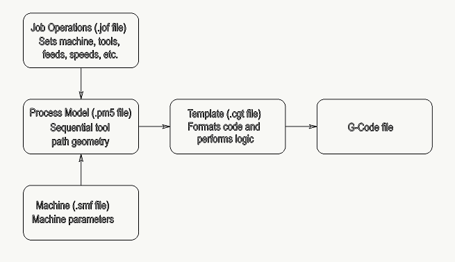
The Code Generator is the system that creates the NC G-Code file for your machines controller. It gathers all of the geometric data from the model, the Job Operations tool and step data and the data for your machines capabilities. Then for each element, or set of elements, the data is processed through the CGT file which formats the information into the code that your controller understands.
How it Works
The Code Generator is the combination of the four files illustrated on the left. The JOF contains data about the tool and the tool parameters. These are used for toolpath in the PM5. Geometric elements created with the JOF parameters are considered toolpath and their data will be processed for G-Code (layer elements are ignored). The SMF contains data about the machines requirements and capabilities. These three files combine data to process through the CGT.
For example, among other things the JOF supplies the speed, feed and offset register to use. The PM5 supplies the graphic view of the line as well as the end point locations. It also maintains the ties between the different files. The SMF supplies some of the code words to use, how to transition between moves and much more. The CGT formats the data into the language that the machines controller understands. The CGT can also perform logic and math functions as well as formatting functions beyond those contained in the SMF.
Try it
Create the following simple toolpath model to see how the files work together. This exercise is based on an inch model in the milling applications but can easily be adapted for any of the product families.
- Start your SmartCAM application and open Process - Planner.
- Add and add the default milling operation and tool. Simply press Accept.
- Click the Operation tab and enter 12 in IPM. Accept.
- Select Job Info. Then select the Machine tab. Select the SMF and CGT files here.
- In the MACHINE directory, select lsmill.smf and lsmill.cgt. These are installed with your application in the SmartCAM data directory. Accept.
- Then Close the Planner.
- On the Insert Bar switch to CAM mode. It will automatically switch to your new step 10.

- Set the offset selector to Left
 .
. - Draw a line from X1.00 Y1.00 Z0 to X2.00 Y1.00 Z0. This will create a horizontal line of one inch with the tool offset to the left. Use Verification to confirm this.
- Use Element Data to see how SmartCAM stores the information about the line.
- Process - Code and the label at the top should already display your machine (SMF and CGT). Enter a Code File name and Create Code.
Use a text editor to view the G-Code file.
- Save this model for use later in this topic.
Here is the flow chart from earlier illustrating the data based on this exercise.
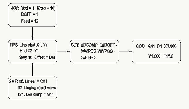
The JOF contains the tool and step numbers, the Doff register number and the cutting feed. The SMF contains the code word for a linear feed move, how to display a rapid transitional move and the code word for left cutter compensation. The PM5 contains the data specific to the line, or linear feed move and assembles the parts of the JOF and SMF where requested. For example applying the step data to the line and using the rapid dogleg motion to display in Verification. Through Process - Code this accumulated data is sent through the CGT which formats it into the G-Code that is understood by the controller.
|
|
Tip
|
The Machine file (SMF)
The SMF file contains information specific to your machine and its controller. It determines items such as numeric formats, machine limits, rotarY-axis information and much more. Some of this data affects how your model reacts during Verification. See the Machine Define topic for more about this utility.
The SMF can be changed at any time. This means that a single model can be used for multiple machines, only rarely needing modification to the model.
Try it
See how the SMF directly affects the models verification animation.
- Open the model from the previous exercise.
- Group the line and Transform - Move with Copy=on.
- From 0 and for To Point enter X=0, Y=2, Z=0, Enter. This will create a copy of the line at 2 inches in the positive Y direction.
- Use Machine Define
 found in your SmartCAM Program Group
to open your SMF (for example mill\machine\lsmill.smf).
found in your SmartCAM Program Group
to open your SMF (for example mill\machine\lsmill.smf). - Scroll to question number 82 and set this to <0> No. Save the SMF.
- Process - Verification
 .
Enable the Draw Rapids feature.
.
Enable the Draw Rapids feature.
- Set the Speed to a slower number and press Start
Note that the dashed rapid lines move in a straight line from the end of the first line to the start of the second line. Close the toolpath simulation window.
- Set question number 82 to <1> Yes and save the SMF. Run the toolpath simulation again.
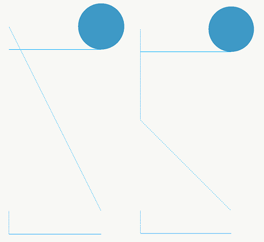
Illustrated on the left is the result of SMF question 82 set to no dogleg moves, on the right it is set to Yes, display dogleg moves. There are many items in the SMF that directly affect the way the model behaves. Be aware of this when creating your models.
The CGT (Code Generator Template) file
The primary function of the CGT file is to format data into the language that is understood by the controller. Because of that, often logic and math is required. This means that the CGT is also very capable of performing logic and math much the same way a standard computer language does.
It also automatically performs some functions that are specific to CNC control language. For example conditional output known as modal output where if a word has already been output and is requested to output again, it will suppress its output.
Try it
See how conditional brackets <> affect code output.
- Open the model from the previous exercise and delete the line or lines. The model should be empty of any geometry.
- With Step 10 create points at the following locations in this order.
X1, Y1
X1, Y2
X2, Y2
X2, Y1
- Use your Tool Motion verification tools to verify that the rapid points travel up the left side, then down the right side.
- Process - Code and edit the code file. It should look similar to this:
G00 G40 G80 G90 T1 M03 S0 X1.0 Y1.0 Z1.0 G00 Y2.0 X2.0 Y1.0 M05 M09 G00 M30 - Use a text editor to edit the CGT file. Find the @RAP section. It should look similar to this:
@RAP < #MOV>< X#XPOS>< Y#YPOS>< Z#ZPOS> @ - Remove the conditional brackets from X#XPOS and Y#YPOS so that it now looks like this:
@RAP < #MOV> X#XPOS Y#YPOS< Z#ZPOS> @ - Process - Code and view the new G-Code file.
 G00 G40 G80 G90
 T1
 M03 S0
 X1.0 Y1.0
 Z1.0
 G00 X1.0 Y1.0
 X1.0 Y2.0
 X2.0 Y2.0
 X2.0 Y1.0
 M05 M09
 G00
 M30
Without the conditional brackets the X and Y words are output every time they are encountered. With the brackets they are only output if the value has changed.
Additional Resources
The following additional resources are available to aid in the maintenance or creation of Code Generators.
- The Technical Support Code Generator
website
Use this site to either find a Code Generator that already works for your needs, or to find one that works as closely as possible to use as a starting point for editing. - The SmartCAM User Email Forum
Join this forum of hundreds of SmartCAM users that frequently share Code Generators and other information. It is also a great resource for other manufacturing information that is not necessarily related to SmartCAM.
Related Topics