Creating Custom Tool Graphics (CTG) Files
SmartCAM provides the ability to define custom tool and holder shapes to be used during Verification. The custom tool graphics are defined by drawing the tool and holder profiles according to a set of prescribed rules, and then saving the CTG as a pm5 file. The CTG file is then associated with a tool using the Edit Tool dialog box.
The CTG tool and holder are used for display and Verification removal volumes only. Toolpath offset calculations use the tool definition as defined by the tool parameters. In Verification's material removal mode, the tool and holder are checked for collisions with the stock and fixture.
This section covers the following topics. Click to go directly to the topic.
Creating and Using a Milling Tool and Holder
This example demonstrates the proper method of defining a milling tool and holder.
Define the tool profile
- Use File - New to start a new session of the SmartCAM application.
- Select the XY_PLANE on the Insert Bar and use Get View to change the view to the TOP view in Milling applications, or RIGHT view in Advanced Turning. In the case of Advanced Turning, use Dynamic View to rotate the view so X points to the right and Y points up toward the top of the screen.
- On the Insert Bar, choose CAD Layer Mode and specify Layer 1.
- Set the Insert Bar Prof Top setting to Off.
- Starting at the coordinate system origin, define the desired tool profile in
the first quadrant. The tool profile should have a general CCW direction, and
should end touching the Y axis at X 0.0. Only Arc and Line element types may
be used to define the profile.
Define the holder profile
- On the Insert Bar, choose CAD Layer Mode and specify Layer 2.
- Define the holder profile in the first quadrant in the same manner as the tool
profile. The holder profile should start and end at X0.0 and have a general CCW direction.
The holder profile does not need to start at the same Y position as the tool profile
end, and may actually overlap the tool profile, if desired.
Save and use the CTG file
- Choose File - Save As, provide a descriptive name and Save the file to the SmartCAM folder containing the milling CTG files. The SmartCAM application only supports one CTG file location, so all CTG files to be used within a single job must reside in the same folder.
- To use the CTG file, edit an existing tool or create a new one, and then select the CTG File field in the Edit Tool dialog box and choose the File Select button. Locate the CTG folder and then select the desired CTG file. The tool preview window will display the CTG tool profile.
- Use Verification to verify a toolpath assigned to the tool associated with the CTG file. To display the tool holder, turn on Show Holder in Verification Options.
Creating and Using a Milling Holder Only
This example demonstrates the proper method of defining a milling holder to be used with a parametrically defined tool. A single holder CTG file can be used with any number of different tools.
Define the holder profile
- Use File - New to start a new session of the SmartCAM application.
- Select the XY_PLANE on the Insert Bar and use Get View to change the view to the TOP view in Milling applications, or RIGHT view in Advanced Turning. In the case of Advanced Turning, use Dynamic View to rotate the view so X points to the right and Y points up toward the top of the screen.
- On the Insert Bar, choose CAD Layer Mode and specify Layer 2.
- Set the Insert Bar Prof Top setting to Off.
- Starting at the coordinate system origin, define the desired holder profile in the first quadrant. The holder profile should have a general CCW direction, and should end touching the Y axis at X 0.0. Only Arc and Line element types may be used to define the profile.
- Using the User Event panel, insert a User Command element before the first
element in the holder profile to signal to the system that the holder profile is to
be translated along the tool axis to the appropriate position, as defined by the Length Preset.
Save and use the CTG file
- Choose File - Save As, provide a descriptive name and Save the file to the SmartCAM folder containing the milling CTG files. The SmartCAM application only supports one CTG file location, so all CTG files to be used within a single job must reside in the same folder.
- To use the CTG file, edit an existing tool or create a new one, and then select the CTG File field in the Edit Tool dialog box and choose the File Select button. Locate the CTG folder and then select the desired CTG file.
- Specify the desired placement of the holder relative the parametrically defined tool by specifying a Length Preset distance. If the tip of the holder was drawn starting at Y0.0 and a Length Preset of 0.0 is specified, the holder tip will be placed at the top of the parametric tool. If the holder is to be placed at a specific distance from the tip of the tool, enter that distance into the Length Preset.
- Use Verification to verify a toolpath assigned to the tool associated with the CTG file. To display the tool holder, turn on Show Holder in Verification Options.
Creating and Using a Punch and Guide
This example demonstrates the proper method of defining a punch and guide, including how to create a cluster punch.
Define the punch profile(s)
- Use File - New to start a new session of SmartCAM.
- Select the XY_PLANE on the Insert Bar and use Get View to change the view to the TOP view.
- On the Insert Bar, choose CAD Layer Mode and specify Layer 1.
- Set the Insert Bar Prof Top setting to Off.
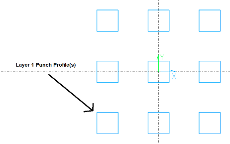
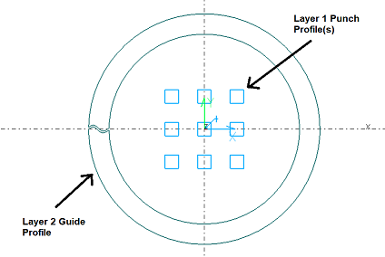
- Draw the tool using lines and arcs. The profile(s) should be closed and have a general CCW direction. For
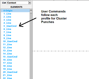
Cluster Punches place a User Command (Create - User Elmts - User Event) after each closed punch profile. The physical location
(X and Y location) is not important, but they must follow the profiles in the database. The Event Text can be blank, or any text.
Define the guide profile
- On the Insert Bar, choose CAD Layer Mode and specify Layer 2.
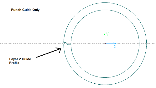
- Define the guide profile in the same manner as the punch profile, placing it in the
desired orientation relative to the X and Y axes. The profile must be closed and
have a general CCW direction.
Save and use the CTG file
- Choose File - Save As, provide a descriptive name and Save the file to the SmartCAM folder containing the fabrication CTG files. The SmartCAM application only supports one CTG file location, so all CTG files to be used within a single job must reside in the same folder.
- To use the CTG file, edit an existing tool or create a new one, and then select the CTG File field in the Edit Tool dialog box and choose the File Select button. Locate the CTG folder and then select the desired CTG file.
- Use Verification to verify a toolpath assigned to the tool associated with the CTG file. To display the tool holder, turn on Show Holder in Verification Options.
Creating and Using a Turning Tool and Holder
This example demonstrates the proper method of defining a turning tool and holder. The same technique is used for fixed hole tools.
Define the tool profile
- Use File - New to start a new session of the SmartCAM turning application.
- Select the XY_PLANE on the Insert Bar and use Get View to change the view to the RIGHT view. Use Dynamic View to rotate the view so X points to the right and Y points up toward the top of the screen.
- On the Insert Bar, choose CAD Layer Mode and specify Layer 1.
- Set the Insert Bar Prof Top setting to Off.
- Define the tool profile in the desired orientation relative the X and Y axes.
When the tool is displayed , the X and Y axes will correspond to the local X and Y axes
of the turning ZX_PLANE. The turning tool radius center should be placed at the
origin position, and the profile should be closed and have a general CCW direction. For
fixed hole tools, place the tool tip at the origin position.
Define the holder profile
- On the Insert Bar, choose CAD Layer Mode and specify Layer 2.
- Define the holder profile in the same manner as the tool profile, placing it in the
desired orientation relative the X and Y axes. When the holder is displayed the X and Y axes will
correspond to the local X and Y axes of the turning ZX_PLANE. The profile should be closed and
have a general CCW direction.
Save and use the CTG file
- Choose File - Save As, provide a descriptive name and Save the file to the SmartCAM folder containing the turning CTG files. The SmartCAM application only supports one CTG file location, so all CTG files to be used within a single job must reside in the same folder.
- To use the CTG file, edit an existing tool or create a new one, and then select the CTG File field in the Edit Tool dialog box and choose the File Select button. Locate the CTG folder and then select the desired CTG file.
- Use Verification to verify a toolpath assigned to the tool associated with the CTG file. To display the tool holder, turn on Show Holder in Verification Options.
Creating and Using an EDM Wire Guide
This example demonstrates the proper method of defining an edm wire guide.
Define the guide profile
- Use File - New to start a new session of the SmartCAM wire edm application.
- Select the XY_PLANE on the Insert Bar.
- On the Insert Bar, choose CAD Layer Mode and specify Layer 2.
- Set the Insert Bar Prof Top setting to Off.
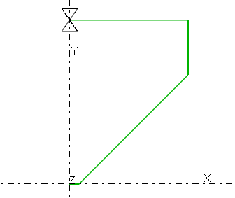
- Starting at the coordinate system origin, define the desired guide profile in
the first quadrant. The guide profile should have a general CCW direction, and
should end touching the Y axis at X 0.0. Only Arc and Line element types may
be used to define the profile. When the guide is displayed, it will be positioned
at the upper guide offset position, and then revolved about the wire axis. A second
copy will be mirrored acros the XY_PLANE and displayed at the lower guide offset position.
Save and use the CTG file
- Choose File - Save As, provide a descriptive name and Save the file to the SmartCAM folder containing the wire edm CTG files. The SmartCAM application only supports one CTG file location, so all CTG files to be used within a single job must reside in the same folder.
- To use the CTG file, edit an existing tool or create a new one, and then select the CTG File field in the Edit Tool dialog box and choose the File Select button. Locate the CTG folder and then select the desired CTG file.
- Use Verification to verify a toolpath assigned to the tool associated with the CTG file. To display the tool holder, turn on Show Holder in Verification Options.
Creating and Using an EDM Hole Electrode
This example demonstrates the proper method of defining a hole electrode.
Define the electrode profile
- Use File - New to start a new session of the SmartCAM wire edm application.
- Select the XY_PLANE on the Insert Bar.
- On the Insert Bar, choose CAD Layer Mode and specify Layer 1.
- Set the Insert Bar Prof Top setting to Off.
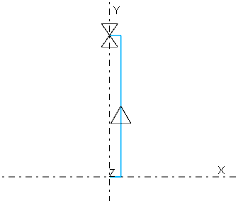
- Starting at the coordinate system origin, define the desired electrode profile in
the first quadrant. The electrod profile should have a general CCW direction, and
should end touching the Y axis at X 0.0. Only Arc and Line element types may
be used to define the profile. When the electrode is displayed, it will be revolved
about the electrode axis.
Define the holder profile
- On the Insert Bar, choose CAD Layer Mode and specify Layer 2.
- Set the Insert Bar Prof Top setting to Off.
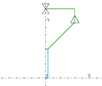
- Starting at the end of the electrode profile, define the desired holder profile in
the first quadrant. The electrode profile should have a general CCW direction, and
should end touching the Y axis at X 0.0. Only Arc and Line element types may
be used to define the profile. When the holder is displayed, it will be revolved
about the electrode axis.
Save and use the CTG file
- Choose File - Save As, provide a descriptive name and Save the file to the SmartCAM folder containing the wire edm CTG files. The SmartCAM application only supports one CTG file location, so all CTG files to be used within a single job must reside in the same folder.
- To use the CTG file, edit an existing tool or create a new one, and then select the CTG File field in the Edit Tool dialog box and choose the File Select button. Locate the CTG folder and then select the desired CTG file.
- Use Verification to verify a toolpath assigned to the tool associated with the CTG
file. To display the tool holder, turn on Show Holder in Verification Options.
Note: Verification will display the defined CTG electrode and holder, however solid material removal will continue to use a cylinder defined by the Kerf Width and tool Length for the material subtraction.
Custom Tool Graphics Rules and Considerations
- Custom tool graphics are defined in the XY_PLANE.
- The tool is defined on Layer 1 and holder on Layer 2. Elements placed on other layers will be ignored.
- Milling tool and holder profiles must be defined in the first quadrant as open profiles sequenced in a CCW direction comprised of arcs and lines only. The tool and holder profiles must start and end at X0.0, with the tool profile starting at Y0.0. This is NOT true for punch and guide CTG models for fabrication.
- Milling Layer 2 holder profile only preceded by User Command element will be positioned at top of parametric tool, if Length Preset is 0.0. If Length Preset is non-zero the holder will be translated along the tool axis by the amount specified.
- Turning tool and holder profiles must be defined as closed profiles sequenced in a CCW direction comprised of arcs and lines only. The turning tool radius and fixed hole tool tip must be centered on the origin.
- If more than one profile exists on Layer 1 only the first profile for each is used except for cluster punches. User Commands are used in this case to define each profile of the cluster punch.
- Co-linear segments are not permitted in the profile, and should be replaced with a single line.
- The parametric tool definition is used for toolpath offsetting, not the CTG tool profile.
- The tool is displayed using the defined Step color and the holder using Tool Holder color defined in the Colors category of the Utilities - Options dialog box.
- CTG files are all contained within the same folder for each model. If you change the location of one, ALL locations are changed within the model or session.