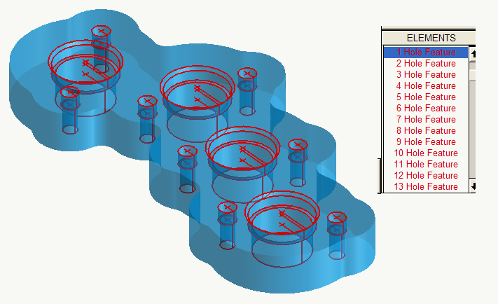
Hole Feature elements from a solid
Hole Feature elements are hole elements with feature parameters that define the hole. These elements 'know' things about the hole like a side angle, chamfer or whether or not it is a through hole. Hole Features can also combine themselves with other Hole Features to define a compound hole (spot drill, drill and countersink, for example). The purpose of these elements is to provide input to the Hole Feature process to automate drilling of these holes.
Hole Feature elements are created contiguously in the element data from the top hole feature to
the lowest. They are selectable as if they were a set of profile elements. You can use the Profile
selection button  , on the Group toolbar, or
double-click any hole feature element of the series and all of the elements of the hole will be put
in the active group. The geometric representation of each element is in such a way that recognition
and selection is simple.
, on the Group toolbar, or
double-click any hole feature element of the series and all of the elements of the hole will be put
in the active group. The geometric representation of each element is in such a way that recognition
and selection is simple.
Use the model below to try this exercise.
| Milling applications | hole_features.pm5 |
|---|
Creating and using Hole Features with a solid model
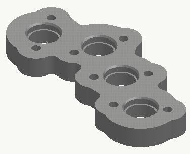
This model contains several compound holes that are easily drilled using Hole Features. It also contains a hidden stock boundary on layer 99 for use with Verification at the end of the exercise.
- Start a SmartCAM milling product and open hole_features.pm5.
- Set the insert property to layer 3. Hole Features use layer geometric features to define hole sections that are directly machinable with Process - Hole Making - Hole Features.
- Select Create - From Solid - Hole and set Match Diameter = No and turn on Entire Solid.
- For Surface on Solid select any surface of the part and press Create All.
Your part should appear as the illustration above. 28 holes are created, these include the counterbores and countersinks.
Drilling the newly created Hole Features
The job with this model already contains the drilling tools required for this part. This exercise demonstrates how to take advantage of the Hole Feature elements.
- Hide the solid part. At this point it is no longer needed and hiding it gets it out of the way of the coming processes.
- Set the insert property to step 1. This is the Spot Drill to be used on all 12 of the parent holes (the top sections).
- Select Process - Hole Making - Hole Feature and set Depth Method = Specify and Depth Type = Spot Diameter.
- Set Depth / Diam = .2. This will create spot diameters just under the smallest .250 diameter holes.
- Group the top section of each hole. You can press
[F10]to get a front view and Box Group the top sections in one operation. - Press Go and all of the holes will be spot drilled.
- New Group. Group the bottom section of each hole. Again, you can box group these from the front view.
- Set the insert property to step 2. This is the .250 diameter drill, the smallest of the 12 parent holes.
- Set Start Level Method = Specify, Depth Method = From Feature and Depth Type = Full Depth.
- Set Start Level = .75. Because the .250 diameter holes start inside the part, specifying the start level will ensure the drilling begins at the top of the part. Go and the holes will be drilled.
- New Group. Individually group the smaller counterbores.
- Set the insert to step 3, the .312 diameter drill to use for these counterbores.
- Set Start Level Method = From Feature. Go and the holes will be counterbored.
- New Group. Group the bottom section of the 4 large holes.
- Set the insert property to step 4. This is the 1.00 diameter drill.
- Set Start Level Method = Specify, Depth Method = From Feature and Depth Type = Full Depth.
- Set Start Level = .75. Go and the holes will be drilled.
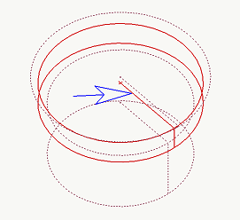
- New Group. Individually group the large counterbores. There are horizontal lines associated
with Hole Feature elements that aid in selection. Use these for selection.
- Set the insert property to step 5. This is the 1.125 diameter counterbore.
- Set Start Level Method = Specify, Depth Method = From Feature and Depth Type = Full Depth.
- Set Start Level = .75. Go and the holes will be counterbored.
- New Group. Individually group the 4 countersinks.
- Set the insert to step 6, the countersink. Set Depth Method = From Feature and Depth Type = Spot Diameter.
- Set Start Level Method = From Feature. Go and the countersinks will be applied.
Use Verification to analyze the job.
Note: The toolpath is NOT optimal, but for the purposes of this exercise, Order Path - Optimize was not demonstrated.
There are many other aspects to Hole Feature machining. There is a Property Change utility that allows changing points or hole element into Hole Features. Hole Feature processes can be recalled through the Modify function for modification and reprocessing. There is a wireframe aspect to Hole Feature element creation using Group Hole.