Editing Curves: Polyarc Fit, Polyline Thin, and Arc/Line Fit
| Supported Applications: | All Applications |
|---|---|
| Time Required: | 20 - 30 minutes |
This exercise will introduce you to some of the Curve editing and simplification features of SmartCAM. These features are used to simplify complex curves into something more manageable and easier to work with and to help reduce the size of your generated NC code files. The emphasis in this "hands-on" exercise is to learn how to work with SmartCAM, not on creating machinable part geometry.
Concepts Explored
- Explode Spline into Polyline
- Polyarc Fit
- Polyline Thin
- Arc/Line Fit
Section One: Start a new Process Model
This exercise assumes a new, empty process model. Use File - New to create a new process model, save any current work as needed. SmartCAM will default to creating geometry on Layer 1.
Section Two: Create a Curved Polyline
The simplification tools being discussed use polylines as the source geometry. So, you will need to create a curved polyline. The easiest method of doing this - for purposes of these exercises - is to create a curved spline and explode it into a polyline.
Open Create - Curves - Spline to open the Spline control panel. Use the following XYZ coordinate values to create a simple curves spline. Use your keyboard Enter key to advance to the next set of XYZ coordinates.
- X: 0.0, Y: 0.0, Z: 0.0
[ENTER] - X: 0.5, Y: 0.5, Z: 0.0
[ENTER] - X: 1.0, Y: 0.0, Z: 0.0
[ENTER] - X: 1.5, Y: -0.5, Z: 0.0
[ENTER] - X: 2.0, Y: 0.0, Z: 0.0
[ENTER]
Use the Go button to create the spline. Press SHIFT+F8 or use
View - Full to zoom into the newly created spline. The spline will look like:

Use the Group Arrow  and select the spline element. Then open Edit - Explode. Set the Explode Level
to
and select the spline element. Then open Edit - Explode. Set the Explode Level
to Polylines and the Tolerance to 0.0010. Then click on
Accept to explode the spline into a polyline.
Notice Element 1, in the List View, changed from Spline to Polyline.
Section Three: Convert Polyline into PolyArc Profile
Open Create - Curves - Polyarc Fit; which is used to create a series of lines and arcs (polyarc profile) that approximates a smooth fit of the polylines in the active group.
Create the new polyarc profile on Layer 2.
On the Polyarc Fit panel, use the following settings:
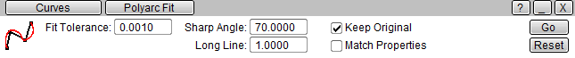
Keep Original is enabled, in order to keep the original polyline. Match Properties is turned off so that you can create the new polyarc profile on layer 2.
Click on Go to create the polyarc profile, on layer 2. Polyarc Fit will create a series of arc and line elements that approximates the original shape of the polyline. Notice the 51 point polyline is converted into 26 lines and arcs.
Section Four: Use Polyline Thin to reduce Polyline Complexity
Sometimes you are working with polylines with a very dense set of control points; perhaps, more dense than is really required to provide the curve shape needed. Polyline Thin can be used to reduce the number of polyline segments in a given polyline or set of polylines.
If you completed the previous Step and used PolyArc Fit, select all the geometry on Layer 2 and hide it or delete it. However, keep the original curves spline on layer 1.
You want to create the new, thinned polyline on Layer 3. So, use the Insert panel and set the CAD layer to 3.
Clear the active group and select the polyline on layer 1.
Open the Create - Curves - Polyline Thin control panel. The Fit Tolerance is used to control how close to the original polyline shape the new thinned polyline must be. A smaller tolerance means the thinned polyline will likely have more control points. For purposes of this exercise, we will use a loose tolerance.
Set the panel to:
- Fit Tolerance: 0.01
- Keep Original: On - so that the original polyline is kept
- Match Properties: Off - so that the new polyline is created on layer 3
Click on Go to create the thinned spline. After creating the spline open Element Data. Notice the original polyline has been recreated using 12 control points. Using Undo and adjusting the Fit Tolerance you can find a sweet spot where the polyline curve is accurate enough for your purposes, but has fewer control points than the original.
Section Five: Using Arc/Line Fit
Arc/Line Fit replaces each circular or linear polyline in the active group with Lines and Arcs. Arc/Line Fit is more single purposed than the Polyarc Fit functionality. It can convert linear polylines into lines and circular polylines into arcs; but it cannot convert a single polyline that contains both linear and curved sections into lines and arcs.
Arc/Line Fit is most often used after slicing a solid or getting the boundary of a solid; often the returned profile is a series of lines with single arc polylines in between them. This functionality allows you to quickly convert all the curved polylines into arcs, without having to worry about the intervening line elements.
To show you how this works, you will quickly create a circular polyline and create an arc element from it.
Use File - New to start a new Process Model. On the default CAD Layer 1, create a single full circle arc.
- Open Geometry - Arc
- Set Center Point to:
0.0, 0.0, 0.0 - Radius:
0.5 - Click on Full Arc button
This will create a circle. Add the circle to the active group and open Edit - Explode.
- Explode Level:
Polylines - Tolerance:
0.0010
Click on Accept to explode the circular arc into a polyline.
You will now convert the circular polyline into an arc. Open the Create - Curves - Arc/Line Fit control panel. Use the following settings:

Click on Go to run the function. When it is complete, you will have the original circular polyline and a new full circle arc element.
Done
This exercise is complete.