Quick Start Exercise: Wire EDM
| Supported Applications: | Advanced Wire EDM |
|---|---|
| Time Required: | 5 - 10 minutes |
 This exercise will lead
you through several common steps used to generate toolpath and create NC code with SmartCAM.
This exercise will lead
you through several common steps used to generate toolpath and create NC code with SmartCAM.
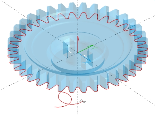
In this exercise, you will load a previously created SmartCAM process model and create a wall offset toolpath, then add lead-in and out moves. The image to the right shows a graphic view of the completed exercise. In this image, the solid model of the gear has transparency enabled to better show the generated toolpath.
In this example, some of the preparatory work has already been completed for you. The existing process model file contains part geometry imported from a CAD modeling system. In this model the boundary curves have been generated and tooling is configured. Additionally, to make this exercise as quick as possible, the final step of adding a glue stop is not shown.
This exercise is meant to give you a brief introduction to SmartCAM machining concepts and to illustrate how quick and easy it is to generate toolpath with SmartCAM. Do not worry if you do not understand exactly why each of the following steps is required, these questions will be cleared up in later exercises.
Concepts Explored
- Load an existing process model
- Selecting Tools and Operations
- Using Wall Offset to generate toolpath
- Inserting Lead-In and Out moves
- Verifying the generated toolpath
- Creating NC code
Step One: Load a Process Model
From the SmartCAM menu, choose File - Open.
In the Open dialog, locate and select qsedm01.pm5.
The Process Model includes a solid representation of a gear and a boundary profile extracted from the gear (on layer 1).
Step Two: Hide the Solid
The gear solid was imported from a modeling package and used to create the boundary profile. It is not needed for the remainder of this exercise. It can be hidden; not displayed, but still in the model. To hide the solid:
- On the status line at the bottom of the SmartCAM window, enable group selection mode with the Group Arrow icon.

- Double-click on any part of the gear solid. The entire gear solid will become highlighted.
- With your mouse in the graphics view, press the right mouse button. Select "Hide Selected" from the pop-up menu.
The solid is hidden and the extracted boundary profile remains.
Step Three: Select the Operation Step
Select the operation step that will be used for the roughing pass around the gear. The Tool and Step are already created with appropriate feeds and speeds.
- On the Insert Properties Bar, click the Step/Layer toggle button and select With
Step from the pop-up menu.
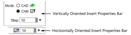
- Select Step 10:Rough from the input field's pop-up pick list. Click on the gray box at the right-side of the Step text input field. This opens a pop-up list of available Steps.
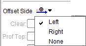
- Set the offset to Left.
Step Four: Generate the offset Toolpath
Using the previously selected Step, generate offset toolpath to profile around the gear.
- From the menu, select Create - Geometry, then select the Wall Offset task from the task set.
- On the Wall Offset panel, make the following settings:
- Wall Input: Profile.
- Wall Side: LEFT
- Wall Repeats: 1
- Distance: 0.0
- Element in Profile: 256
Type in "256" and hit the Enter key to trigger the result. You can also select element 256 from the input field's pop-up pick list, or from the List view - it is the first element in the Wireframe Profile under Layer 2.
When finished the toolpath is displayed in the graphics view. The toolpath elements are included in the List View; elements 405 to 553.
Step Five: Add the Lead-In/Out
The toolpath is generated, but needs a lead-in and lead-out.
- From the menu, select Edit - Geo Edit, then select the Lead In/Out task from the task set.
- On the Lead In/Out control panel, select the Classic tab.
- Set the Lead list to BOTH
- Set the Style to ARC
- Angle: -180
- Radius: 0.25
- Element: 405
Type in "405" and hit the Enter key to trigger the result. You can also select element "405 Arc_CCW" from the input field's pop-up pick list or from the List view.
Step Six: Verify the Toolpath
Use Verification to verify your toolpath, before generating NC code.
- Select View - Get View and then click on Iso. This sets a Isometric view.
- Select View - Full which fits all the graphics in the graphics view.
- Select Process - Verification
- Set Speed: to 2
- Click the Play button.
During verification, you can change the play back speed by typing in a digit, between 0 and 9, or clicking on the "+" and "-" buttons to increment or decrement the speed. Press spacebar to pause simulation and again to restart. Use the normal mouse/keyboard dynamic view functions to change your view as the simulation runs.
Step Seven: Generate NC Code
The format of the NC code is controlled by the selected SMF/CGT file pair. For this tutorial you will use pre-configured files that are shipped with SmartCAM.
- Select Process - Code
- Select a path and filename to store the NC code. You can enter the path directly into the "Code File:" input field or click File Select to display a File Open dialog.
- Click Choose to open the Job Information dialog box.
- On the Machine tab, click SMF File, to make it active, then click File Select.
- Pick the lswire.smf file from the list of available files.
If you do not find this file, or any SMF files, make sure you are looking in the directory where you extracted the Learning SmartCAM sample data, or in your SmartCAM common files directory. - Repeat using CGT File to select the CGT file. Select lswire.cgt.
- Accept the selections. The 'Machine=' status now shows 'LSWIRE.SMF'.
- Enable Open Code File, so that when the NC code file is generated it will be opened in your default code editor. This feature uses Windows File Association, if a valid text editor is not mapped to your NC code file extension, then you will be prompted to establish the association.
- Click Create Code to generate the NC code.
- Click Close to close the Code panel.
The NC code file is generated and stored at the path you provided. You can open it with any text editor.
Done
This exercise is complete.